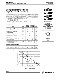
 Collector–Emitter Saturation Voltage - VCE(sat) = 1. DC Current Gain - hFE = 20 – 70 IC = 4 Adc. So, you should a Speaker protector circuit, too.īesides this, we introduce these easy projects. Sometimes, you may like them.Designed for general–purpose switching and amplifier applications. It may cause oscillated noise more easily. Because power transistors can tolerate a voltage of no more than 60V. It makes the voltage of the power supply up to 38.17V. Change the voltage of the secondary transformer to 27V CT 27V 3A. Because they are small size but have high power. You may use TIP3055 and TIP2955 instead of 2N3055 and MJ2955. But if you use LF351, low-cost high-speed JFET input operational amplifier. 2N3055 Amplifier Circuit with PCB | 60W. See the prototype of 50W amplifier circuit. Oscillation or noise within the circuit. Check the B-E extension wires of the power output Transistors. Transistors – Q1 and Q3 may be broken in an open circuit.ģ. Transistors – Q2 and Q4 may be broken in an internal short circuit. Transistors – Q2 and Q4 may be broken in open-circuit, not runs. Transistors – Q1 and Q3 may be broken in an internal short circuit. Sometimes the circuit may not work as expected. Connect speakers and enter signals to the input of this amplifier circuit.
Now you are done with the customization process.Rotate VR2 until reading the meter at 20mA (approx).

Measure the current of the circuit with the Ammeter. Then, adjust Idle current with rotating VR2.If non-zero, indicating that the bad output transistors. Then, Put these output transistors into this circuit.We need to figure out why the voltage is not zero.And, Measure voltage between the output speaker and ground point. TIP3055 Datasheet Using Warnings Note: Please check their parameters and pin configuration before replacing them in your circuit. Because the op-amp IC1 requires this regulated voltage supply. TIP3055 Datasheet You can download the datasheet the link given below. Use a voltmeter to measure the voltage at ZD1 and ZD2.Connect the power supply to the circuit.Why does not put the transistors? Because while the transistors are working. Except, do not put IC1(LF351) and power output transistors Q3(2N3055) and Q4(MJ2955).


 0 kommentar(er)
